 (Standard - Custom)
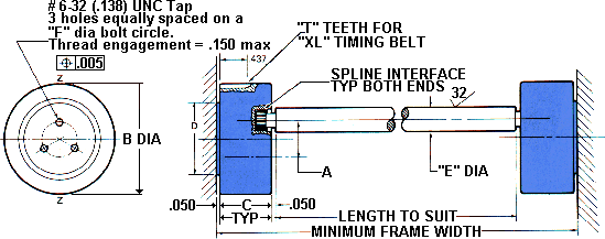
- axis Z-Z denotes shaft travel plane.
- All exterior surfaces to be anodized or black endurion.
- All bearings ABEC 3 and shielded.
- Special sizes available on request.
- Standard assemblies consist of a pair of Mini-SLIMB bearings
with a connecting shaf as shown. Shaft length is determined by customer.
- Alternate drive SLIMB bearing, other than a timing belt
drive, available on request . . . worm and worm gear drives, spur gear
drives, etc.
Maximum Travel
(inches)
A |
Model
No. |
Load
Rating
lbs.* |
B |
C |
D |
E** |
F |
T |
| .500 |
4MSS-2-4 |
20 |
1.381 |
.762 |
1.000 |
.2500 |
.562 |
22 |
| .625 |
5MSS-3-4 |
30 |
1.508 |
.840 |
1.000 |
.2500 |
.562 |
24 |
| .750 |
6MSS-4-6 |
40 |
1.763 |
.860 |
1.125 |
.3750 |
.594 |
28 |
| .792 |
6.3MSS-4-6 |
40 |
1.763 |
.860 |
1.125 |
.3750 |
.594 |
28 |
| .875 |
7MSS-5-6 |
55 |
1.890 |
.888 |
1.312 |
.3750 |
.812 |
30 |
| 1.000 |
8MSS-7-6 |
75 |
2.017 |
.888 |
1.500 |
.3750 |
.875 |
32 |
| 1.250 |
10MSS-12-7 |
125 |
2.272 |
1.000 |
1.750 |
.4375 |
1.125 |
36 |
ALL DIMENSIONS IN INCHES
* Load rating is a maximum allowable working load, statistically
applied for each Mini-SLIMB. A pair of Mini-SLIMBs will support a symmetrically
applied load of double this value. For dynamic applications, consult Yorkshire
Engineering for allowable loading, lubrication, bearing life, etc.
** +.0000, -.0005

 Applications
| Standard Bearings
| Drive Bearings
| Roll Assemblies
| Powered Rolls
Applications
| Standard Bearings
| Drive Bearings
| Roll Assemblies
| Powered Rolls
Simplified Drive Systems
| Wrenches
| Information Request
Form | Ordering
Information | Main SLIMB Page
About Yorkshire
Yorkshire Industries, Inc.
P.O. Box 5100
Andover, MA 01810
Toll Free: 1-888-475-1949
Fax: 978-688-5348
solutions@yorkshireind.com