|
Procedures For The
Design, Analysis And Auditing
Of Static Control Flooring/Footwear Systems
Stephen L. Fowler
Fowler Associates, 3551 Moore-Duncan Hwy, Moore, SC 29369
Tel: 864-574-6415, FAX: 864-576-4992, Email: sfowler@sfowler.com
William G. Klein
K&S Laboratories, 2026 Bay Rd., Stoughton, MA 02072
Tel: 617-341-8331, FAX: 617-341-8331, Email: kslabs@thecia.net
Larry Fromm
Hewlett Packard, 1501 Page Mill Rd., Palo Alto, CA 94304
Abstract - It is the purpose of this paper to show that the electrostatic
performance of footwear/flooring systems, defined as the electrostatic potential
of personnel arising out of the use of these systems, can be predicted with
adequate precision based on component resistance data alone, and further to
present resistance testing methodologies which are at once more relevant and
more reproducible than most in common usage today. Conclusions, which are to
a considerable extent a matter of opinion though based on hard data, suggest
that inappropriately defined criteria and overly stringent specification are
significant problems today to users, suppliers, and auditors.
Background and Introduction
It is generally accepted that the resistance and triboelectric properties
of footwear and flooring materials together constitute the main parts of the
system which limit the electrostatic body voltage of a person walking on the
floor. Charge decay time may also be inferred from resistance data. Unfortunately,
the use of resistance to predict or define quantitatively the electrostatic
performance of flooring/footwear systems has been fraught with many problems.
The problems are not trivial because the industry-wide failure to establish
appropriate standards for the measurement of components and the performance
of systems and the consequent use of various methodologies yielding significantly
different values have often led to serious difficulties. These difficulties
have resulted, for example, in both failed installations and expensive claims
of failure not based on "true" criteria of performance. It is not
possible to set up universally useful standardized criteria for product design,
field performance, or auditing procedures without a significant degree of basic
knowledge and an agreement within the ESD community as to the specific, quantifiable
objectives toward which these criteria are aimed. With different manufacturers
and different users playing by different rules, chaos has resulted.
Past work (2,3) has addressed some of the
difficulties and has suggested solutions in defining relevant criteria for the
design and evaluation of static controlled flooring, footwear, and flooring/footwear
systems. It has not, however, had any noticeable effect on the way that floors
and shoes are specified and tested, nor has there been any systematic effort
to reconcile the troublesome differences. It is well understood that the rule
of thumb for personnel voltages of a hard grounded worker are as follows: at
100 Meg W the personnel voltages may
be over 100 Volts ; at 10 Meg W personnel
voltages will usually be less than 100 Volts; at 1 Meg W
the expected personnel voltages are in the 10 Volt range. Flooring and footwear
systems are more complex than a simple wriststrap grounded situation. The current
work expands on past work, introduces new methodologies which are both reproducible
and relevant, and verifies the assertions made with quantitative data from both
the laboratory and operative factory installations. A critical examination will
be made as to how some currently used test methodologies fit into this picture,
specifically ESD 7.1, ASTM F-150, NFPA 99, ESD 9.1 and IEC 1340-4-1. It is hoped
that this work will be sufficiently intriguing to lead to a concerted effort
to develop and promulgate a performance oriented set of specifications and more
universally accepted evaluation and auditing procedures.
This work is aimed equally at those whose good fortune it is to have the freedom
to write specifications for new installations and those tortured souls who must
make critical choices and compromises in the utilization, modification, or scrapping
of existing non-conforming flooring.
< top >
Basic System Analysis
In order to intelligently approach the issue of specifying and evaluating
the resistance properties of footwear and flooring as they affect body voltages,
it is necessary to have some reasonable idea as to how these properties act
and interact together with other pertinent system parameters. This is a highly
complex problem for which there is no easy solution. Briefly, some common deficiencies
of often cited analyses consist of:
- the concept of linear, lumped parameters when they are in fact neither linear
nor lumped;
- neglect or inadequate definition of important variables; and
- the use of a steady state approach to a dynamic event.
The list could go on. An example of this sort of specious reasoning is the
popular representation of the human walker as a parallel plate capacitor with
constant charge. Although it is tempting to use such a configuration, which
sort of looks like a foot on the floor and is simple electrically, it suffers
from all three deficiencies mentioned above and has virtually no analytical
value. It is well beyond both the scope and purpose of this paper to delve deeply
into this issue. Rather, we shall simply attempt to put the problem into a proper
perspective so that the simplifications used to deal with the area of very low
personnel static will be both credible and useful.
Figure 1: Equivalent Circuit
Figure (1) shows a highly simplified "equivalent" circuit7 of a
person walking on a floor surface. It is presented here not as a model from
which to make calculations, but as a demonstration tool to indicate the complexity
of the general problem and as a basis for useful further simplification in the
special case of interest here, a high degree of static control resulting in
very low body voltages. The static potential on the individual is the result
of the interfacial EMF's due to triboelectrification, the surface neutralization
at the foot/floor interface where the foot is down, and the flow of current
through the same interface in response to a body potential to ground. While
it is conventional to consider this flow, and therefore the body resistance
to ground, to be the main controlling factor in limiting body voltage this is
strictly true only for body charges originating from sources other than the
shoe and floor. In order to segregate the effects of dissipation to ground and
minimization of surface accumulation of charge, body voltages under dynamic
conditions were measured with the various flooring/footwear combinations in
a normal manner and also with the body insulated from ground by nonconductive
shoe inserts. Maximum body voltages will be quantitatively characterized by
shoe sole resistance, floor surface resistance, and body to ground resistance.
It will be shown that, for the resistance levels used in static controlled systems,
the surface resistances of the sole and floor are the main controlling factors.
Since our interest here is more than academic, it will be necessary to define
and justify our test methodologies for both body voltage and resistances.
< top >
Test Methodologies
A. Measurement of Body Potential
Since body potential is taken in this work to be the criterion of electrostatic
performance in a floor/shoe system, it is imperative that there be an understanding
of the way that it is generated, measured, and reported. First, the measuring
equipment must possess certain basic properties. It must not constitute in
itself a significant electrical part of the body/footwear/floor system and
its frequency response must be sufficient to capture the voltage pattern without
distortion. Both of these conditions were satisfied by the equipment used in
this work. It is of interest to note here that some test runs were performed
with bandwidths of both 5Hz and 100KHz with no discernible difference in peak
value readings. Peak values were determined in two ways, from a new versatile
peak hold LED array instrument and by observation of an oscilloscope trace.
For the body of the work, a 100KHz bandwidth was used.
The manner in which the test voltage is generated is important. Figure 2
is a sketch of the means.
A person holding a probe walks on a test surface wearing test shoes and his
peak voltage is recorded. This procedure has been rather generally used for
a large number of years. Except for the peak voltage criterion, it is the same
as that required by AATCC TM-13412, which calls for a damped response, and
it is substantially the same as a Work in Process standard of the ESD Association.
Basically, both say the same thing: if you want to find out what happens when
you walk on a floor, walk on it and see.
Figure 2: Body Voltage Test Method
The differences among various methodologies presented in the literature reside
in the prescribed method of walking for test purposes. While this is not usually
a significant factor, it can be. In this work we have adopted a brisk natural
gait for tests made in the field and a brisk, short, slightly high step for
laboratory work where one can hardly walk naturally on a three or four foot
square test specimen. This lab step produces, as observed on an oscilloscope,
the highest voltages short of doing anything really wild.
These procedures clearly exaggerate the danger of any real human body discharge,
at least statistically, as they involve high generation motions and define
peak values of very short duration which, in any likely real life situation,
would not be seen by a sensitive device.
< top >
B. Shoe Resistances
Three types of resistance measurement have been used to characterize the
resistance properties of shoes. The ESD Association has a method S9.18 which
involves lining a shoe with foil, loading it with metal shot, and measuring
the resistance to a base plate from the foil. We have found that this method
does not adequately represent the body resistance from shoe to ground in normal
wear. We have not used that method in this work. Previous work (2,3)
has demonstrated the measurement of body resistance to ground using an actual
body. This is also the general methodology of the ANSI Z-419 standard and is
one type of evaluation we use here. The third method is one we also use - the
measurement of shoe sole surface resistance. This has been described in other
work (3) but has been slightly modified by the use of a convenient step-on
floor test unit which gives rapid, reproducible results and is suitable for
on site testing. It may also be hand held as shown. This procedure is diagrammed
in Figure 3.
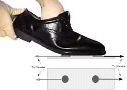
Figure 3: Sole Surface Resistance Measurement
< top >
C. The Measurement of Flooring Resistance
It is critical that the measurement of the resistance of flooring be capable
of producing reproducible results anywhere, any time, and by anyone, assuming
samples of reasonably similar properties as this is a main criterion in virtually
all specifications and audits. Today this is far from the case with the use
of different methodologies as well as considerable variations even when nominally
using the same method. As will be shown later, considerable variations in resistance
properties may not be of great functional significance, but specifications
must be made and standards must be met. Too often a material hovers between
acceptance and rejection based on who makes the test and when. Four methods
are in common use today, NFPA 99, ASTM F-150, ESD 7.1 and IEC 1340-4-1. 6,10,11
All are quite similar and are based on NFPA 99, using identical 2 1/2 inch,
5 pound electrodes (except for the IEC method which uses a 2 inch, 5 kg electrode).
Aside from the differences in specified voltages and environmental conditions
(100 or 500 volts, 12 or 50% RH), which could easily be reconciled by discussion,
their fundamental flaw is the electrodes. They simply do not simulate the feet.
The light weight and relatively hard surface of the NFPA electrodes render
the resistance readings significantly sensitive to surface unevenness and even
minor surface contamination. Much higher variability accompanies the use of
a 100 volt test potential as in ESD 7.1, although this does seem like a reasonable
level considering the intended purpose. Our test results from the lab and in
the field indicate that more relevant and more reproducible results can be
obtained by the use of heel electrodes rather than the 5 pound weights. The
type of heel electrode used, which is now commercially available, is shown
in Figure 4.
Figure 4: Heel Electrode
< top >
The area of the conductive contact is the same as that of the conventional
electrodes and is made from heel grounder material. The pressure of the contact
from body weight and the relative softness of the electrode both tend to produce
a good electrical contact, just as a heel grounder or ESD shoe sole would do.
Another advantage of this method is the great speed with which readings can be
taken, thus encouraging large samplings which can be legitimately quantified statistically.
Another important advantage is the virtual elimination of bias in floor resistance
testing. Most auditors will, when they find a bad spot, wiggle the electrode a
little or move it to an adjacent spot to try to get a good reading. This is probably
legitimate from a functional point of view, but does leave too much room for personal
judgment. It should be noted that, as described in previous work (2), significant
surface homogeneity of resistance demands a modified electrode material for proper
evaluation.
Figure 5 shows the surface to ground readings on a vinyl tile panel where 21 marked
points were tested by the methodologies of ESD 7.1 and with heel electrodes, both
at 100 volts.
Figure 5: Heel Electrode vs. S7.1 Electrode
The difference is obvious. It is not clear how much this difference would
matter functionally, but it would certainly be important if you had a 1 or
2 Megohm specification to meet.
Figures 6 and 7 show comparative results on a much less conductive vinyl
using both 100 and 500 volts with the ESD/NFPA electrodes and both surface-to-surface
and surface-to-ground configurations.
It can be stated that in general that the heel electrode methodology using
100 Volts yields resistance readings which are lower and less variable than
S7.1 type tests at 100 Volts. On average, the values obtained at 100 Volts
using the heel electrodes tend towards those of the 500 Volt, 5 lb. electrode
tests, but with less variability.
Figure 6: Heel Electrode vs. S7.1 Electrode
Figure 7: Heel Electrodes vs. S7.1 Electrodes
Figure 8 shows the ordered values for an audit-type run at a major electronic
manufacturing facility.
Figure 8: Audit Data -- Surface-to-Ground
It contains approximately 285 observations made on a vinyl tiled floor. It
is worthy of note for two reasons. First, because it contains so much more
data than is usually amassed in a single area audit, a valid statistical analysis
is possible; and second, because it takes one man with meter and computer in
hand only about 30 minutes to do this job.
It should also be noted here that this installation outright failed the user's
specification for resistance and yet, with proper footwear easily met the performance
requirement of body potentials below 100 volts. The quantitative explanation
for this is to be found in the experimental work reported in the next section.
< top >
Body Voltage Test Results
The following data was generated in two ways. First there is laboratory work
under controlled conditions and with limited sample size and second, in the
field under normal working conditions. Figure 9 summarizes the laboratory data.
| |
|
|
Voltage Generated (Volts) |
| |
|
|
Floor Coverings |
| |
|
|
|
Conductive Flooring |
|
|
| Shoe Sole |
|
Footwear Resistance (Ohms) |
Alum-inum
Plate |
Viny l#1F |
Vinyl #2F |
Carpet |
PVC #1M |
Lab Floor Nylon |
Control Nylon |
|
| |
Sole |
To Gnd |
Feet Insulated From Shoes |
| Neolite |
1.0E12 |
>3.0E11 |
2500 |
3500 |
4000 |
600 |
600 |
2000 |
7500 |
| Plain PU |
3.0E10 |
>3.0E11 |
130 |
1300 |
1500 |
800 |
70 |
680 |
2100 |
| SD PU |
9.0E8 |
>3.0E11 |
20 |
220 |
240 |
40 |
20 |
390 |
3200 |
| S6699 |
5.0E7 |
>3.0E11 |
2 |
60 |
80 |
20 |
30 |
50 |
2400 |
| Rubber #2 |
1.6E5 |
>3.0E11 |
20 |
170 |
300 |
90 |
55 |
210 |
7000 |
| O.R. |
1.4E5 |
>3.0E11 |
55 |
100 |
150 |
60 |
15 |
150 |
2400 |
| |
|
|
Shoes Worn In Normal Manner |
| Neolite |
1.0E12 |
3.0E11 |
2500 |
3500 |
4500 |
600 |
400 |
2000 |
7500 |
| Plain PU |
3.0E10 |
8.0E9 |
130 |
1000 |
1100 |
700 |
60 |
420 |
2000 |
| SD PU |
9.0E08 |
5.0E7 |
13 |
75 |
80 |
40 |
15 |
340 |
2500 |
| S6699 |
5.0E07 |
2.0E6 |
1 |
20 |
30 |
5 |
30 |
50 |
2000 |
| Rubber #2 |
1.6E05 |
6.0E5 |
1 |
50 |
80 |
30 |
15 |
175 |
6500 |
| O.R. |
1.4E05 |
4.0E5 |
1 |
20 |
20 |
5 |
15 |
120 |
2000 |
|
Floor Covering Surface
Resistance (Ohms) |
1 |
5.0E5 |
1.0E7 |
3.0E7 |
7.0E9 |
4.0E10 |
1.0E12 |
Figure 9: Flooring/Footwear Body Voltage Test Data
It shows peak voltages on a test individual with footwear and floor resistances
defined and measured as described above under two different body /shoe relationships,
normal wear and with both feet insulated from the shoes by means of high resistance
polyethylene booties.
Figure 10 is a chart giving the conversion of resistance data from engineering
notation to logarithms.
|
Shoe |
Resistance - W |
Log R |
Resistance - W |
Log R |
| |
Sole |
Sole |
To Ground |
To Ground |
|
Neolite |
1.0E12 |
12.00 |
3.0E11 |
11.48 |
|
Plain PU |
3.0E10 |
10.48 |
8.0E9 |
9.90 |
|
SD PU |
9.0E8 |
8.95 |
5.0E7 |
7.70 |
|
S6699 |
5.0E7 |
7.70 |
2.0E6 |
6.30 |
|
Rubber #2 |
1.6E5 |
5.20 |
6.0E5 |
5.78 |
|
O.R. |
1.4E5 |
5.14 |
4.0E5 |
5.60 |
|
Floor Covering
|
Resistance |
Log R |
|
Aluminum Plate |
1 |
0.00 |
|
Vinyl #1F |
5.0E5 |
5.70 |
|
Vinyl #2F |
1.0E7 |
7.00 |
|
Carpet |
3.0E7 |
7.48 |
|
PVC #1M |
7.0E9 |
9.85 |
|
Lab Floor-Nylon |
4.0E10 |
10.60 |
|
Nylon Control |
1.0E12 |
12.00 |
|
|
|
|
|
|
|
Figure 10: Resistance Conversion to Log R
< top >
We prefer the logarithmic form because it is a continuum which is easier for
most people to grasp intuitively than powers of ten with multipliers. We further
believe that it is preferable to avoid the use of such terms as "static dissipative"
and "conductive" to define quantitative ranges. It would certainly be
wrong to consider the nylon carpet in the laboratory to be static dissipative
in the same sense as more conductive flooring, and a similar statement can be
made about the plain polyurethane shoe soles, although also nominally in the SD
category. The term "static dissipative" should be reserved for qualitative
assessments.
Figure 11 shows quite impressively that the static development on the individual
is strongly controlled by the combination of shoe sole surface resistance and
floor surface resistance, as the body was effectively insulated from the floor
and from ground for all of these tests (>1011 Ohms).
Figure 11: Feet Insulated From Shoes
The control resides in mutual conductivity at the shoe/floor interface. This
contention is reinforced by Figures 12a and 12b which for clarity have an expanded
scale and the high resistance has been removed. In this case there is a significant
conductive path from the body through the shoes.
Figure 12a: Shoes Worn In A Normal Manner
Figure 12b: Shoes Worn In A Normal Manner (detail)
Although the voltages are lower, they are not much lower. This brings into
question the wisdom of characterizing shoe resistance by body to ground resistance
alone, as is usual, when a major part of the shoe/floor control resides in the
shoe/floor interface without regard to body-to-ground resistance. Body-to-ground
resistance is a fairly good indicator of static performance in most cases but
this is due to the usual correlation between sole surface resistance and resistance
through the shoe. (See figure 9) Such a correlation need not be, however, and
an ideal shoe may, in most situations, have a highly conductive sole and a very
modest resistance from body to ground. There is no implication intended that
vertical resistance is unimportant, simply that it may not play a major role
in that static whose origin is the floor/shoe interface
Figure 13: Audit Data
Figure 13 is a depiction of the effects of foot grounding systems and mode
of usage in two different carpeted assembly and test areas of a medical electronics
manufacturing plant. The test subject was the ESD supervisor.
< top >
The legends on the graph are defined as:
- "none" = no heel grounders -street shoes
- "HG Norm" = heel grounders on both feet and walking in
a normal manner
- "HG Care" = heel grounders on both shoes and walking with
extreme care to perform heel-toe movements.
- "Toe/Heel" = each shoe had a combination heel and toe grounder
attached , normal walking manner
Because the measured resistances were so far out of specification, heel grounders
were required on the assumption that they would be more effective than ESD shoes.
The supervisor reluctantly removed his grounders and was clocked at 1200 peak
volts walking normally in the test bench area. With heel grounders his potential
dropped to 250 in one installation and 450 in the other, these being the peaks
when both heels left the floor, as they did with nearly every step. When care
was taken not to allow simultaneous contact loss with both grounders the values
were 40 and 170 volts respectively. When he used a sole grounder, which is essentially
a combination of heel and toe grounders, the peak voltage in both cases dropped
below 30 volts. A sole grounder creates what is really a conductive sole shoe
with no opportunity for the basic, high generating sole to take part and no
possibility of a momentary loss of contact. Controlling the source, the floor/shoe
generator, is a major factor. Figure 14 graphs additional data from the same
installation with additional footwear and operators.
Figure 14a:
Figure 14b:
Figure 14c:
From these data it can be seen that either of two pairs of shoes produced
very little static. There is little choice electrically among the sole grounder
and the two more conductive shoes. It is apparent that the more conductive soles
were able to exploit the "local" surface conductivity of the carpet,
but that's another story.
How hazardous are the peak values associated with foot grounders? As before,
we don't really know. It's a judgment call again, but what does a performance
standard requiring personnel voltages to be maintained below 100 volts mean
in a case like this, and how should it be audited?
While we have dwelled on the control of foot generated static and have shown
that body-to-ground resistance plays only a minor role, other potential sources
must not be neglected. If proper protocol is not followed, seating/clothing
static, for example, can be considerable and calls for a body grounding mechanism
whether ground strap or shoe/floor. If "good" clothing and "good"
seating are used, the grounding needs are small, even as with a good shoe/floor
combination. Figure 15 shows the grounding requirement for a very lively smock/seat
combination.
Figure 15: Control of Clothing/Seating Static
The voltage on an individual wearing high resistance clothing was monitored
as he quickly arose from a high resistance chair, keeping insulative shoes immobile
on the floor, and with varying wrist grounder resistances. Peak voltages were
of very short duration for resistance values below 109
W and essentially disappeared for values
below 107 W.
Does this mean that a value of less than 107 W
is necessary to protect against peak voltages? Again, probably not, but the
offending furniture and clothing should be addressed.
< top >
Conclusions and Recommendations
Today too many people still consider floors and footwear independently. Floors
and Footwear must be chosen as a system. A good floor will not cover
up bad footwear, nor will good footwear cover up a bad floor.
Present 5 lb. weight electrodes are not adequate for judging floor performance.
Floor resistance should be measured using the heel electrode methodology at
100 Volts. This method is more representative and reproducible. This due to
the weight of the electrodes being more representative of those experienced
in normal applications and due to the ease of use especially for large floor
areas.
Present definitions and therefore test methodology for determining performance
of footwear is inadequate. As a result shoe construction is often far from optimum.
The shoe has been considered a monolithic device when in fact it must perform
two nearly independent functions. First it should provide an electrical connection
between the person and the floor without compromising electrical safety for
the person. Second its shoe/floor interface must provide for a rapid recombination
of generated charge. The following shoe construction is recommended for optimum
performance:
Outer sole surface resistance should ideally be less than 107
W . The more conductive the outer sole
the better as more recombination of charge occurs (and thus lower personnel
voltages). The only limiting factor should be the floor marking concerns of
highly carbon loaded sole materials or other physical considerations.
The midsole construction of the shoe should be insulative enough to obviate
any electrical safety concerns.
Users find it confusing that the resistance limits for defining conductive floors
are very different from those for defining conductive packaging. Terms like
"dissipative" and "conductive" are not necessary nor helpful.
A continuous scale of resistance should used.
Present methodology for determining flooring resistance is inadequate.
a. Floor resistance to ground should be less than 108
W as measured with the heel electrodes
at 100 Volts for optimum performance.
b. The construction of the floor and the grounding system should be insulative
enough to obviate any electrical safety concerns
All audits must include an evaluation of static potential on the person appearing
from all causes as well as an audit of contributing factors, such as shoe and
floor resistances.
< top >
Appendix
Tips for ESD Flooring Installations
Because the electrical properties of floors depend so greatly on installation,
the following comments are made:
It is likely that most ESD coordinators or consultants only get one or two
opportunities to influence the choice of ESD Flooring and its installation process
during their tenure. This is such an expensive, critical job that some key considerations
must be addressed.
- ESD Coordinators must be proactive. It is too late
to specify the floor after it is installed. This means working with Corporate
Real Estate in addition to local facilities personnel. Being proactive is necessary
to avoid ESD considerations being just an afterthought. It is much easier to get
the job done right when involved from the very beginning. Remember: you will have
to live with the floor and its ESD Audit performance for several years.
- Understand the floor preparation processes, the installation
processes, and cleaning/maintenance processes. These are critical to having a
successful project. Make sure the floor has a moisture emission test performed
prior to the selection of the ESD floor. Follow the manufacturer's instructions
carefully for floor preparation, installation and electrically grounding.
- Use only qualified installers. One of the most important
aspects of the installation is the adhesive in regards to spreading, curing and
coverage.
- Maintain records of measured resistance. No traffic
should be allowed on vinyl or epoxy floors before curing is complete.
- After 48 hours evaluate the installed floor. Make
a sketch of the area ahead of time showing the measurement points.
References
- Klein, William G., "Floor Generated Static-A Resistance
Limited Phenomenon," Compliance Engineering, Fall 1991.
- Fowler, Stephen L. and William G. Klein, "Static Phenomena
and Test Methods for Static Controlled Floors," EOS/ESD Symposium Proceedings,
1992.
- Klein, William G., "Performance Oriented Design and
Test Procedures for Static Control Footwear," EOS/ESD Symposium Proceedings,
1993.
- Freeman, P.S. and R.Y. Moss, " Sources of Error in
Resistance Measurements on Conductive Flooring," EOS/ESD Symposium Proceedings,
1991.
- Hewlett Packard Document A-5951-1589-1, "Workmanship
Specifications for ESD Control," Revision F, Appendices M and O.
- ESD Association Standard 7.1, "Floor Resistance-Resistive
Characterization of Materials".
- Janszen, Arthur, Unpublished Work, Brunswick Corporation,
1967.
- ESD Association Standard 9.1, "Footwear-Resistive Characterization".
- ANSI Z-41, Safety Footwear.
- NFPA 99, Health Care Facilities.
- ASTM F-150, Electrical Resistance of Conductive Resilient
Flooring.
- AATCC 134, Static Propensity of Carpets.
< top >
|