
PTF Material Performance and Reliability
Just because Polymer Thick Film technology is low cost does not mean that it is low quality. With Poly-Flex Circuits, it's just the opposite. Our materials formulated by our Research and Development group are extensively tested for high performance and reliability. Materials have been refined over years of high volume production - the benefit of having manufacturing and material development under the same roof. Batch to batch consistency is ensured via our tightly controlled in-house mixing facility.
This section is intended to give the reader greater appreciation for the reliability of Poly-Flex's Polymer Thick Film circuits by understanding the reliability tests performed on the materials. Unlike the copper based circuitry, there are few industry standard methods and criteria for Polymer Thick Film (PTF) reliability testing. Moreover, few PTF manufacturers perform reliability testing to any significant extent. As a pioneer of PTF technology, Poly-Flex Circuits takes reliability very seriously. Our inks and adhesives are subjected to very aggressive accelerated aging tests. They must show virtually no change from their original state - <20% change from initial resistance value is a common criteria.
The tests described in this section have been performed during our material qualification program. Many of these test are also used as process controls in the material mixing, printing or component assembly operations.
Silver Inks
The test results described below are for Poly-Flex's standard production silver filled ink.
Print Quality
Poly-Flex inks are formulated to run at very fast rates on our high speed production print presses. This speed advantage translates to a cost advantage over printing inks that are not tuned to high speed printing. Moreover, our inks are formulated for long screen life to eliminate ink waste and unnecessary changeovers due to ink drying. When formulating a new ink, our Research and Development Chemists work with the production printers from conception through final qualification. Circuits are fabricated at normal production printing speeds over the course of a production shift. Samples taken at different time intervals are visually inspected for print quality. Line definition must be good with no pin holes observed on any of the samples. This test is repeated with different ink batches and longer production runs during the scale up phase.
Resistivity
Poly-Flex inks provide resistivity from 10 to 20mOhms/square/mil. The ink resitivity is determined by measuring the resistance and ink height on a standard 600 square test pattern.
Adhesion and Abrasion Resistance to Untreated Polyester
Poly-Flex Circuits' printed inks are formulated to provide excellent adhesion to untreated polyester, eliminating the need for expensive print treatments required for inferior inks. Our inks also demonstrate excellent surface hardness - a property vital to a robust membrane switch. The tests described below are used during ink formulation as well as process controls for ink mixing and production printing.
Adhesion, ASTM D 3359
A standard test pattern (square block) of silver ink is printed and cured on untreated polyester. A cross hatch (knife blade) is used to cut through the ink. A tape is then placed over the cut area, allowed to stand for 60 seconds and then pulled off. The samples are then examined for any missing pieces of printed ink. All samples must exhibit 100% adhesion.
Abrasion, ASTM D 3363
This method is used to determine the pencil hardness equivalent of the ink. A Paul Gardner test apparatus is used to ensure repeatability of the results. Typically, this test can vary by +/- 1 hardness grade. A minimum hardness of 2H is required. Standard inks measure 3H to 4H.
Adhesion and Resistivity Over Dielectric
Some product applications require conductive crossover traces. Standard 600 square test samples were printed over Poly-Flex's dielectrics. Adhesion and resistivity were tested per the methods described above. Adhesion was 100% in all cases. Resistivity was within 10% of the ink-on-polyester value.
Crease Resistance
This test was used to determine the change in resistance of a conductive ink circuit trace after a crease in both tension and compression. Samples were printed on 0.005 inch (125um) polyester using a standard 600 square serpentine pattern. The samples were folded and a 500g weight was placed at the fold for 60 seconds. Resistance measurements were taken prior to testing and 15 seconds after removal of the 500g weight. The change in resistance was less than 10%. Test samples were visually examined under 30X magnification with no evidence of cracking or delamination.
Repeated Flex, UL 746E
The purpose of this test was to determine the durability of a conductive ink trace (with and without a cover coat dielectric) when flexed 180 degrees around a 1/8" (3mm) mandrel. The test sample is flexed so that the conductive ink is in tension or compression. The test samples were subjected to 50 cycles. The data is reported as the average percent increase in resistance of the samples. Without dielectric, the resistance increased less than 7%; with dielectric, less than 12%. Test samples were visually examined under 30X magnification with no evidence of cracking or delamination.
Accelerated Aging Tests
The purpose of this test was to determine the performance of conductive ink when subjected to specific accelerated tests that simulate product aging, shipping and storage environments.
Thermal Shock
Thermal Shock was performed per MIL-STD-1344, Method 1003, 25 cycles, -55C to +85C, 30 minute soak at each extreme, less than a 5 minute transfer time between temperature extremes. This test simulates the thermal excursions that may be seen during shipping or actual usage for some products. 600 square serpentine coupons were used for this test.
High Temperature Aging
The test was performed per MIL-STD-202, Method 108A, +85C for 500 hours, less than 20% humidity. This condition simulates long term application in high temperature storage conditions. 600 square serpentine coupons were used for this test.
Accelerated Aging Test Results
Test
Conditions
Duration
% Resistance Change From Initial Value
Thermal Shock
-55C/+85C, 30 min soak, <5min transfer
25 cycles
-7%
High Temperature Aging
+85C
500 hours
-5%
High Temperature / Humidity
This test simulates long term application in high humidity environments. It is run in conjunction with the Poly-Solder® conductive adhesive. Tests were conducted for 1000 hours each at the following conditions: 60C/90%RH, 70C/85RH, 85C/85RH. The junction resistance of components mounted with Poly-Solder ® was monitored. All samples passed the criteria of less than 20% increase in junction resistance over the 1000 hours. See the Component Attachment Section for further details.
Pre-Aging Flex Test
The purpose of this test was to determine the durability of a conductive ink trace (with and without a cover coat dielectric) after being subjected to the thermal shock and high temperature aging tests described above. Following the aging tests, samples were flexed 180 degrees around a 1/8" (3mm) diameter mandrel, both in tension and compression. Test samples were subjected to 50 cycles. The results, expressed as percent increase in resistance, are as follows:
Condition
Compression
Tension
Thermal Shock, no dielectric
8%
11%
Thermal Shock, with dielectric
8%
9%
High Temp Aging, no dielectric
4%
7%
SMT Component Attachment (Poly-Solder® and PF200)
Poly-Flex attaches Surface Mount Technology (SMT) components to flexible circuits using its patented Poly-Solder® Isotropic Conductive Adhesive. After curing of Poly-Solder®, the PF200 mechanical strain relief encapsulant is applied to permit extreme circuit flexing without degradation of the component junctions.
Poly-Solder® was specifically formulated to form stable junctions to standard SMT components, even in very humid environments, without special metalization. It is this patented high temperature / humidity performance that differentiates Poly-Solder® from inferior conductive adhesives. Its reliability has been proven over many years of testing and high volume production. Over 75 million components per year have been attached using Poly-Solder®.
Die Shear Strength, MIL-STD-883, Method 2019.5
The adhesion strength is tested by applying a force laterally to a component (that has been mounted with Poly-Solder ®) until it is sheared from the substrate. Both a lab scale / material control test and a production process control test have been established. Both tests are performed without the PF200 mechanical strain relief material applied.
Production Test: A corresponding production process control test uses a chip component (resistor, LED or capacitor) placed into stenciled conductive adhesive pads on polyester. Off-the-shelf components with standard Pb metalization are used. Adhesion values correlate to component package size and lead type:
Package Style
Lead Style
Package Size
Average
Adhesion (lbs)
Chip Component
Formed Metalization
0603
5.5
Chip Component
Formed Metalization
0805
7.0
Chip Component
Formed Metalization
1206
8.0
1206 LED
Gull wing
1206
7.0
High Temperature / Humidity
This test simulates long term application in high humidity environments. In order to monitor the component junction resistance, a daisy chain test vehicle was developed. This circuit incorporated 10 zero ohm resistors connected in series, a daisy chain PLCC44 (50 mil pitch) and a daisy chain QFP80 (25 mil pitch)
Poly-Solder® was tested with and without PF200. The test circuit pattern was printed on 5 mil (125um) polyester using Poly-Flex's silver ink. The conductive adhesive was stenciled on the polyester and the SMT components attached. PF200 was applied to half the circuits. The series chain resistance for each component type was monitored during exposure to high temperature and humidity using a four wire measurement technique. The pass/fail criteria was less than 20% increase in junction resistance over 1000 hours exposure. Results are as follows.
Test Conditions
Without PF200
With PF200
60C, 90%RH, 1000 hrs
100% Pass
100% Pass
75C, 85% RH, 1000 hrs
100% Pass
100% Pass
85C, 85%RH, 1000 hrs
100% Pass
100% Pass
Poly-Solder was then tested against two commercially available conductive adhesives, without PF 200. Both commercial materials shorted on the QFP80 component due to poor material printability. Poly-Solder® did not exhibit short circuit conditions as it was developed for fine pitch printing applications. The test circuits were exposed to 85C, 85%RH. Results were as follows:
Material
Resistors
PLCC44
QFP80
Conductive Adhesive A
Failed <96hrs
Failed<96hrs
N/A (shorted)
Conductive Adhesive B
Failed <240hrs
Failed <300hrs
N/A (shorted)
Polysolder®
Passed >1000 hrs
Passed >1000hrs
Passed >1000hrs
Numerous third party studies have also concluded that Poly-Solder® has much better temperature and humidity performance than other commercially available materials.
Accelerated Aging with Flexural Stress
This test simulates the flex stress a circuit may see during handling or end application. The test vehicle was a functional circuit containing two LED's and two resistors, mounted with Poly-Solder ® and encapsulated with PF200 strain relief material. These circuits were wrapped around a 0.5 inch (12.5mm) diameter mandrel to apply stress to the component area. Circuits were functionally tested and then subjected to the tests listed below. The circuits were functionally tested after environmental exposure.
Test
Conditions
Duration
Results
Thermal Shock
-50C/+85C, 30 min soak, < 5 min transfer
25 cycles
100% Pass
High Temperature & Humidity
+75C/85%RH
1000 hours
100% Pass
Thermal Cycle
-50C/+85C, 12 hr soak, <30 min transfer
40cycles hours
1000% Pass
Flip Chip
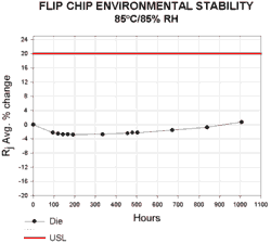
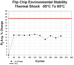
Poly-Solder® has also been qualified for Flip Chip die attachment. A Flip Chip test vehicle was developed similar to the SMT circuit described above. The FB250 die from Flip Chip Technologies was selected as the test die, and a corresponding circuit was designed. This die is 0.250" per side with 48 SnPb bumps on 20 mil pitch.
The die were placed into printed Poly-Solder® and cured. Underfill was then dispensed and cured. The circuits were exposed to 1000 hrs 85C/85%RH and 250 cycles of Thermal Shock (-55C/+85C, 30 min soak, 10 second transition). Results are as follows:
Dielectric Materials
General
Dielectric materials provide mechanical protection of conductive traces, electrical isolation of adjacent conductors and electrical insulation between conductive layers. While most polymer dielectric can provide some degree of mechanical protection, their isolation and insulation properties are most critical to the long-term reliability of circuits with silver conductive traces, in high temperature/ humidity environments.
High temperature and humidity with an electrical bias has become a generally accepted standard for product life and reliability growth testing. Failure mechanisms, such as corrosion and ion mobility, can be triggered by the effects of these conditions. This testing was used by our research chemists to develop (and make improvements) to PF114 "hydrophobic" dielectric for telecommunication and appliance applications.
Insulation Resistance Testing
Case 1 - Sample circuits were produced with Poly-Flex PF012 silver and PF114 dielectric inks, and with similar materials from a commercial manufacturer. The separation between conductors on the samples was .015" at their closest point. The circuits were sent to an independent lab to perform 70ºC and 85%RH 1000 hour testing with a 10 VDC bias between adjacent conductors. A leakage current of >20uA was considered a failure.
Circuits with the commercial dielectric coating exhibited a steady increase of leakage current until exceeding the 20uA limit at 400 hours. The circuits exhibited severe discoloration with evidence of electromigration (dendritic growth.)
The circuits manufactured with Poly-Flex materials continued to 1000 hours with a minimal increase of leakage current. When removed from the environmental chamber the circuits showed little discoloration and no evidence of electromigration.
Case 2 - A manufacturer of appliances subjected flex circuits manufactured by Poly-Flex to the following temperature/ humidity sequence for a total of 1000 hours with a 20VDC bias:
TEMP.
HUMIDITY
SOAK
+70 º C
50% RH
2 HOURS
+45 º C
98% RH
2 HOURS
+85 º C
85% RH
2 HOURS
+25 º C
35% RH
2 HOURS
All test samples passed functionality requirements at the conclusion of the accelerated testing. Some water residue was present on the samples, but no dendritic growth was evident.
Isolation Resistance Testing
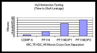
The following graph shows the results of high temperature immersion testing of a commercially available dielectric material vs. the standard PF114 dielectric in production today, and improved versions of PF114 that will be released into production this year. Each test sample contained 400 cross over points. This extreme test (developed by PFC) allowed our chemists to quickly determine the effect of formula modifications.
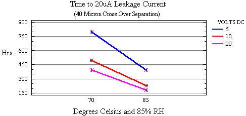
The following graph shows the effects of both temperature and voltage acceleration factors on polymer thick film materials using 400 cross point test samples. These data were helpful in predicting long-term product reliability, and provided a base line for materials improvement.
Other White Papers


