
Baggy Edge Removal
Our basic BERS System consists of a SLIMB Bearing roll system which is utilized
to correct the effects of a baggy edge, i.e., re-distribute the tensile
stress profile.
The gross tension of the web is redistributed in such a way that the
previously baggy edge becomes fully stressed or tight . . . eliminating
the common wrinkle problem . . . all the while maintaining normal tracking.
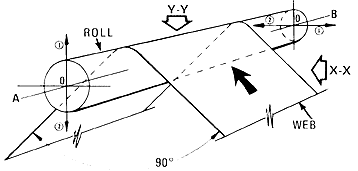
 1. Vertical motion of side
-- A effects baggy edge removal (on either side). |
The web, after experiencing some roll wrap, will always attempt to exit that roll perpendicular to the roll axis since the roll surface velocity component is perpendicular to the axis. It can be seen above that the apparent exit angles are equal and opposite resulting from the compound motion of the SLIMB Bearings. Hence, the web will continue to track straight and true and experience some web spreading action as well. If the inputs are opposite to those shown above, the same BERS System characteristics are generated in the opposite direction with the same results.

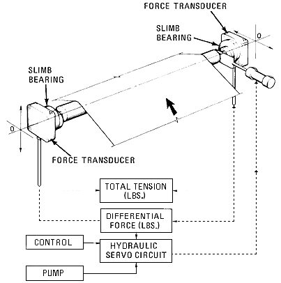
A fully automatic BERS System utilizes two SLIMB Bearings to support the roll whose relative motions are the same as previously described. However, automatic actuation is provided by a hydraulic cylinder incorporated in the above servo circuit which is coupled directly to the roll shaft.
Two DCDT force transducers are mounted between the SLIMB Bearings and the machine frame. The transducers measure the resultant reaction force caused by the web wrap.
When the web is stressed evenly across its full width, the signals are balanced and the system is stabilized. However, when an uneven tension profile occurs, the force signals become unbalanced and the difference between these two force signals is fed to a servo system. In turn, the hydraulic cylinder repositions the BERS System until the web is stressed evenly across its full width and the system is balanced.
The response rate is fully proportional, i.e. for small errors or signal differences, the system will respond slowly and for large force signal differences, which may occur during a splice, the response rate becomes rapid.
Baggy Center Removal
Installation
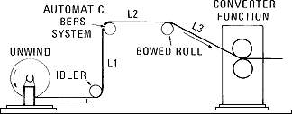
Shown is a typical TPC installation having an unwind stand, Auto
BERS System with its typical 90 degree web wrap and the bowed roll located
immediately upstream of a converter function or nip roll station.

Lead in and exit distances to and from the Auto BERS Roll, L1 and L2, are typically 1/2 to 1 web width and should be approximately equal. If these distances are less than 1/2 web width, then they must be equal.
Longer lead in and exit distances increase the effectiveness range of the system, i.e., if L1 and L2 = 1 web width, the system remains effective for approximately one web width downstream of the bow for most materials. Conversely, shorter distances result in a reduced effectiveness range. Since the spreading action of the bow disipates rapidly, L1 and L2 are generally in the range of 1/2 web width.
The lead in distance from the bow to the control zone L3, should equal 1/2L2. See Yorkshire for exact recommendations.